Risk Management

Adventures in Development Testing Part 1

All Fingers and Thumbs
How to assess the risk of an unavoidable finger trap

Anyone who has designed anything with moving parts will know a thing or two about finger traps. We look for anywhere where a finger could accidentally be inserted into a product and try to avoid the possibility of finger insertion in places where mechanical forces might be applied that could result in injury or worst case severing of the digit. Always the preferred solution is to design out the finger trap completely.

But how do you assess injury risk where a finger trap is unavoidable? 

We recently developed a product where a trap was unavoidable. This occurs when 2 components are hinged away from each other with spring-assisted closure. We needed to understand whether the minimum spring force required for the parts to reliably and repeatedly close would cause injury, if opened to the maximum possible extent, and then released onto an inserted finger. To complicate matters further the hinge is not a fixed hinge but instead comprises 2 sprung retaining cables with compound curves for mating surfaces. So the arc of travel is complex and likely to be different every time the hinge is opened.

Calibrating force against displacement

Our first step was to define ‘acceptable’ forces. What are the forces that can be applied to a finger before bruising, fracturing or breakage occurs or before permanent damage is inflicted? Surprisingly these forces do not appear to be defined in standards – we eventually discovered a couple of research papers that identified these force limits in the context of electric window mechanisms for cars. Gory reading but evidentially very credible!


For our tests to be realistic, we needed to recreate the point loading that would occur if a finger were placed in harm’s way and find a way to measure the force applied to the finger. After a lot of thought we adopted the following approach:-

  1. We cast several sizes of simplified test ‘fingers’ in soft silicone

  2. We calibrated the fingers by compressing them in our tensile test machine recording the force applied at increments of deflection

  3. We built a test rig to retain the test finger at various positions within the hinged joint. Our high-speed camera, operating at 1000 frames per second, was mounted to the rig perpendicular to the rotation of the hinge to capture the point of maximum deflection of the silicone finger as the hinge was released under the force of spring-loading.

  4. We were able to measure the deflection on the recorded high-speed footage at the point of maximum compression of the finger and extrapolate the force from the tensile test machine calibration tests. 

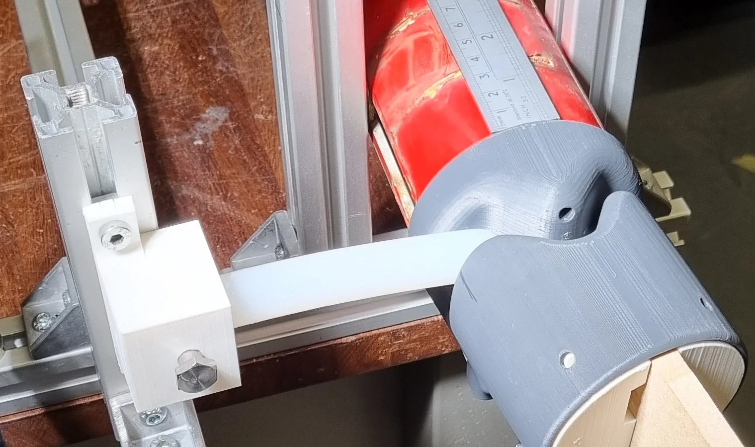
Test rig to retain the test finger at various positions within the hinged joint

Chronos 1.4 High-Speed Camera

The slow-mo video shown at the top is slowed 35x - the real time duration of the video is 0.3 seconds. If the slow-mo video looks alarming, keep in mind that the silicone fingers are not intended to be compressively representative of real fingers. We went for the softest silicone to maximise deformation so that our measurements could be as accurate as possible.
Sorry if it makes you wince!

TRL’s – Why Hardware and Product Start-ups need to use them… carefully.

The first Technology Readiness Level scale (TRL) was developed by NASA in the 70s to assess the maturity of a technology prior to integrating this technology into a system. These days the most widely used variant is composed of 9 levels, which categorise the progress of the development of a technology from basic research into first principles (TRL1) through to level 9 when a technology is in its final form and is ready for commercial deployment.

I’m not going into a detailed description of the standard 9 TRL scale here – there are loads of sites that can help with this. This infographic produced by Dick Elsy for the HWM Catapult gives a basic overview.

The TRL metric is increasingly used by all stakeholders in the development of every kind of technology, product and even service as a way to define business maturity. Potential Investors will increasingly define a minimum TRL before which they will not engage. Government manufacturing sector strategy has been steered by TRLs – the High Value Manufacturing Catapults have been established to focus on the Applied R&D stages between TRL4 and TRL6. And many grants and funding mechanisms define application suitability using TRLs.

So it’s worth all start-ups mapping their position and intended trajectory against the TRL system and not only for external communication. TRL’s are a useful project planning and tracking tool.

Nevertheless, care should be taken with their use for three reasons:

Variance between TRL systems.
Beware! There is no standardised definition. So be sure to check that all stakeholders are singing from the same hymn sheet.

Readiness Level Proliferation.
In his seminal book on the subject of measuring technology maturity ‘Did I Ever Tell you about the Whale’, William Nolte coins the term readiness level proliferation to describe ‘the tendency of managers to create variants of the classic TRL to help measure and manage specific programmatic areas of concern’. That’s kind of him – I suspect many are invented by consultants so that they can lay claim to the invention of a ‘new’ system.
So we have (to name but a few) Investment Readiness Levels, Product Readiness Levels, Market Readiness Levels, Manufacturing Readiness Levels and specialist variants such as Software Technology Readiness Levels.

There is some established correlation between some of these systems. For example, the Engineering and Manufacturing Readiness Levels shown in the table below comprises 9 levels, correlating approximately with TRLs 4 to 9. But these correlations are inconsistent between systems that are inconsistent themselves.


How Long is the Piece of String?
Let’s take an electronic product as the example. It has a chipset which is a proprietary component and is therefore, as an individual component, at TRL9.
It is mounted to a PCB as part of an assembly of electronic components that is not yet optimised for mass production and is currently somewhere between TRL6 and TRL8.
The whole is housed in a demonstration housing that has been produced in batch volumes using vacuum casting and is therefore not in design intent material. The housings are screwed together because sonic welding is not an option with thermosets. The housings have been designed to spec but have only been tested in simulation. So the housings could be said to be somewhere between TRL3 and TRL5.

To Conclude…
TRLs are an established means to measure maturity with widespread acceptance and use throughout business and industry. It is important, if only to be credible, to understand what they are and to be able to position your business, technology, or product on the scale. To be certain that they do not trip you up I advise the following:

  • Always ensure that all parties in a conversation about TRLs have the same definitions. Never just use the headline titles – drill down and define the specifics of your own case.

  • Map using whichever readiness level system is most valid to your investor or partner but make sure the logic is sound so that it can translate across systems from technology to investor to manufacturing.

  • Define clear stage gates to move from one level to another. Don’t rely on heuristic assessment – all stage gate requirements should be measurable.

  • Be clear which elements of your development are at which stage and NEVER, NEVER overstate.